Garrattfan's Modelrailroading Pages
Fairlie Merddin Emrys
5.6 Pickups and testing
 |
|
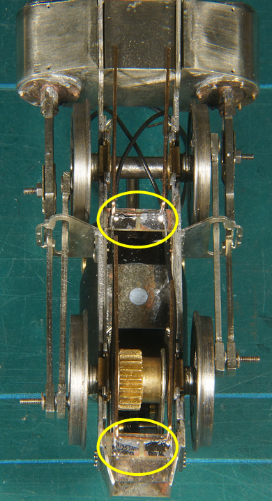
A view from a different angle The wipers are bent in the form of a downturned U, with four angles to prevent interference with the frameplates. I kept the two opposite wipers together because it makes soldering easier. The length of the wire is kept somewhat oversize. First the wipers are soldered into place and than the wire connecting the wipers to the motor. Note that the wipers |
|
| were glued with 5 minute epoxy so it is absolutely essential to solder quickly before the heat transfers to the glue on the other side of the board. Epoxy does not respond well to heat and the board may come off if you linger too long with the soldering iron. | |
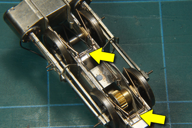 |
The wipers are bent outward. It is important to tune them so that they move all the way with the wheels. When satisfied the the wiper pairs are separated with a flush cutter (arrow) and cut to length with the flush along the wheel rims. Finally the wires are connected to motor. Check the polarity of the motor (does the unit run the right way). |
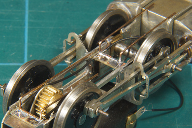
| Testing the unit was pretty simple. Previous test have shown that the unit already runs well. I noticed some wobbly behaviour in both axles and concluded that the quartering was not spot on but that it was compensated by the axleboxes which have a little play in the hornblocks. So I fixated them and verily the unit would not run anymore, there was binding! So I worked on that until it run evenly with the axleboxes fixed temporarily. Once that was done I released the axleboxes again and another test run gave me the satisfying sight of a complete unit running smoothly. | |
From here I started building the second unit. Contrary to the manual I won't be doing the detailing until all testing of the complete locomotive has been done. I also did not fit the front buffer beam permanently as I need to to take the unit apart for painting. |
|

Sign my
GuestBook